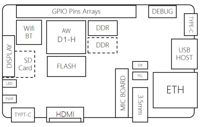
Introduction to development board hardware
*The firmware used in the following content introduction is the D1-H Nezha development board v0.5 release version firmware, and the JD9366AB LCD screen driver is selected in the kernel.
*Firmware download address: D1-H哪吒开发板测试固件20210416
*ee the schematic diagram of the development board: D1-H哪吒开发板原理图20210520
Connection diagram
D1-H-Nezha development board, like a Swiss army knife, can be connected to many external devices.。
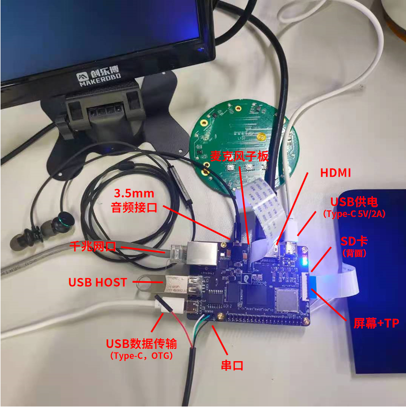
USB
There is a USB HOST and two Type-C USB ports on the board, among them:
(1) The one next to HDMI can only be used for power supply, and the input voltage/current is 5V/2A;
(2) The USB Type-C next to the serial cable is used for data transmission, which can be used for firmware programming, device information programming, ADB shell, adb push/pull and other operations. It can also supply power. The power supply depends mainly on the PC USB port. The current output can generally meet the system startup requirements, but the power supply may be insufficient under some functions, such as MIPI-DSI screens, etc., which need to be plugged in 5V/2A to stabilize the power supply;
(3) USB HOST can be used to plug in U disk, USB camera, mouse, keyboard, etc., following the standard USB 2.0 protocol.
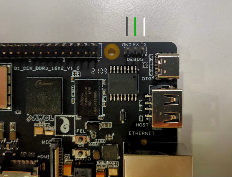
Serial port
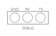
The UART port on the development board has 3 pins, namely GND, RX, TX, and each plug is printed on the body of the development board to correspond to the function
The line sequence of the official FT232R and CH340 serial port is: black-GND, green-RX, white-TX, and red is the power supply. There is no need to plug it here. The specific connection is as shown in the figure below.
e serial port to USB driver needs to be installed when the Windows PC uses the serial cable
When inserting the serial port, the PC will recognize the serial chip model. The serial chip model given by the development kit is FT232R or CH341SER (internal test developer version)
For serial port driver download, please refer to: 串口驱动
You can also search for the serial port driver by yourself or use your own serial port cable. It is recommended to use a 3.3V serial port cable.
Baud rate: 115200
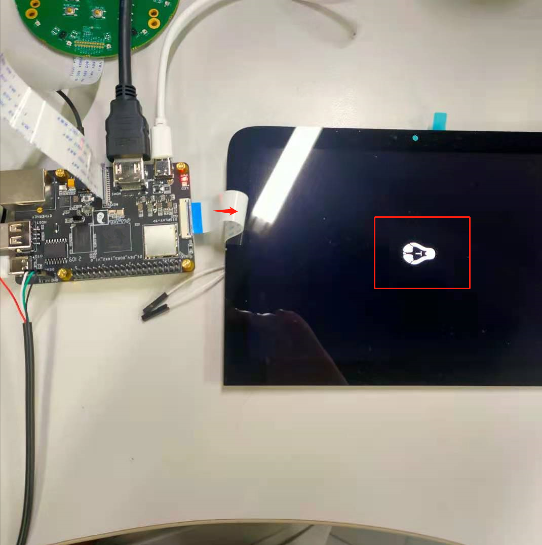
Display interface
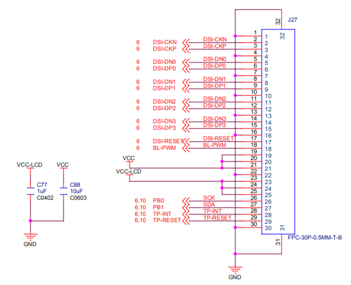
The display interface can be connected to the MIPI-DSI screen and touch. The line sequence is as follows:
The default firmware of the development board is the display interface output. If it is a non-display interface output or is changed to an HDMI output, you can use the following command to switch to the display interface output:
cd /sys/kernel/debug/dispdbg
echo disp0 > name; echo switch1 > command; echo 1 4 0 0 0x4 0x101 0 0 0 8 > param; echo 1 > start;
echo 1 4 0 0 0x4 0x101 0 0 0 8 > param;——The first parameter here, 1 represents MIPI-DSI output, if you want to switch to HDMI output, change to 4
Use the default firmware, the Tina Linux penguin logo will be displayed at startup
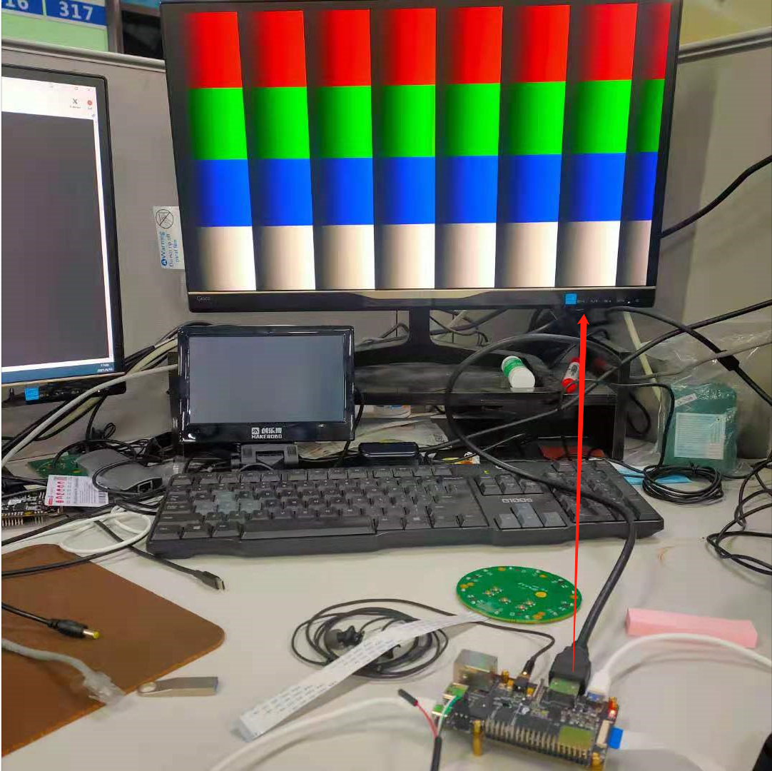
show colorbar
echo 1 > /sys/class/disp/disp/attr/colorbar
play local video:
tplayerdemo /usr/lib/tt-data/01-1080P-HEVC-AAC-60F.mkv
HDMI
Switch to HDMI output:
cd /sys/kernel/debug/dispdbg
echo disp0 > name; echo switch1 > command; echo 4 10 0 0 0x4 0x101 0 0 0 8 > param; echo 1 > start;
The test shows the colorbar:
echo 1 > /sys/class/disp/disp/attr/colorbar
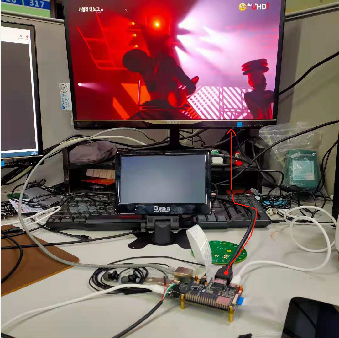
Test of playing video:
tplayerdemo /usr/lib/tt-data/01-1080P-HEVC-AAC-60F.mkv
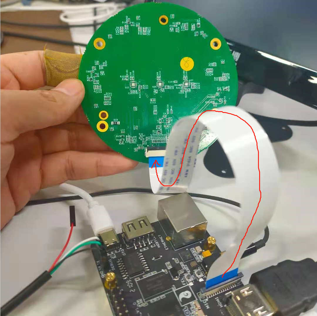
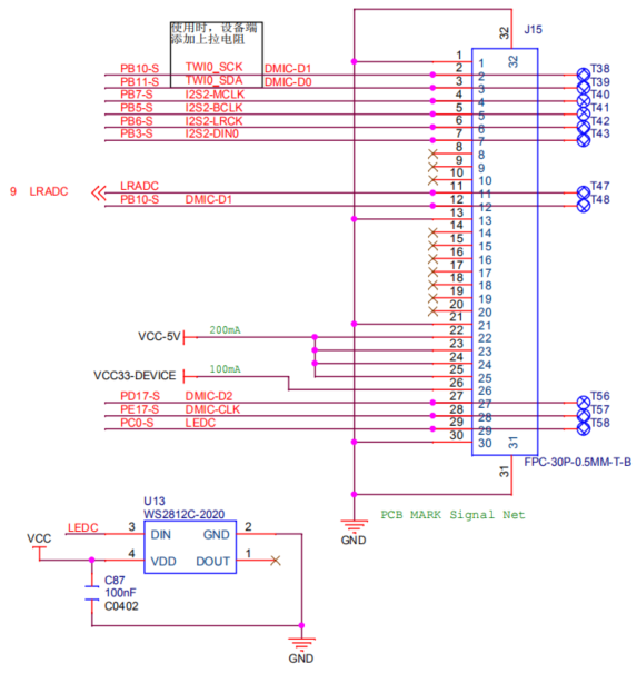
Microphone daughter board
The connection of the microphone daughter board is shown in the figure:
The recording commands are as follows:
//使用arecord命令,在设备硬件设备snddmic上录一个采样率为16000、格式为S16_LE、6声道的音频文件,存到/tmp/test.wav
//Use command arecord tio record a sample tate 16000, format S16_LE, 6 channel audio file in snddmic, save to tmp/test.wav
arecord -D hw:snddmic -r 16000 -f S16_LE -c 6 /tmp/test.wav
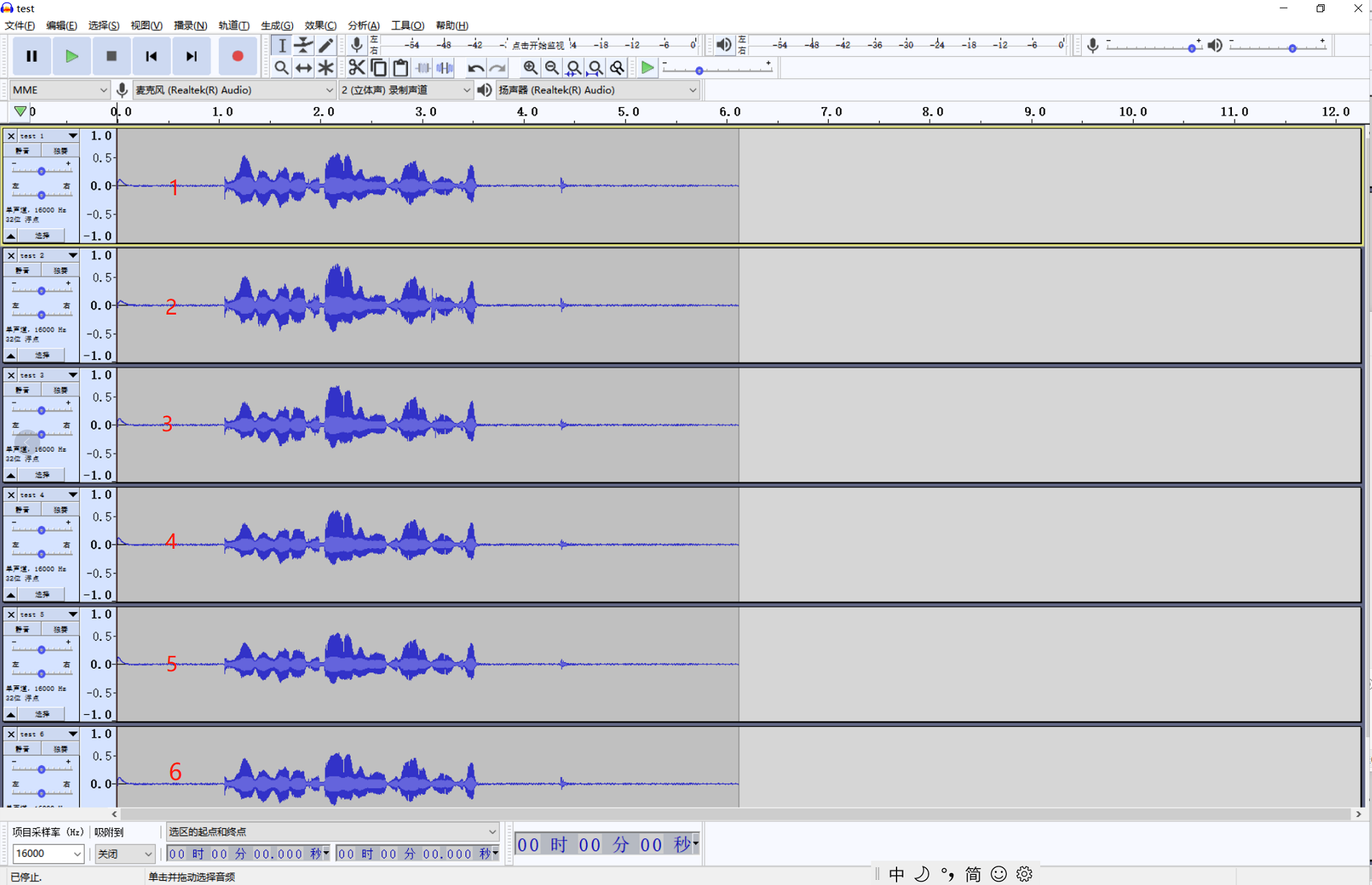
Use adb pull to pull the audio file to the PC and open it with the audio processing software Audacity. You can see that the recorded 6-channel sound is as follows:
The wiring sequence of the microphone daughter board is as follows:
3.5mm headphone port
As shown in the diagram, plug in headphones or other 3.5mm audio equipment to play audio. The command is as follows:
aplay /usr/lib/tt-data/16000-mono-s16_le.wav
*The 3.5mm interface supported by the D1-H Nezha development board is American Standard (CTIA), that is, left, right, ground, and Mic from the inside to the outside. At present, the mainstream mobile phone headset interfaces are all American standards.
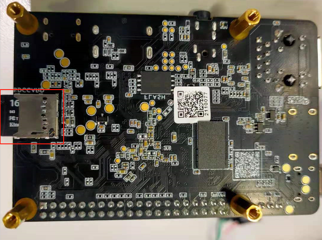
SD card
The SD card slot is on the back of the development board. Insert the SD card to read the data in the SD card.
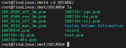
The data of the SD card will be automatically hung in the /mnt/SDCARD directory, and cd /mnt/SDCARD can be carded to the files under the SD card:
Ethernet network port
The Ethernet interface can be used by plugging in the crystal head network cable that can access the Internet, as shown in the figure:
D1-H Tina v0.5 beta version
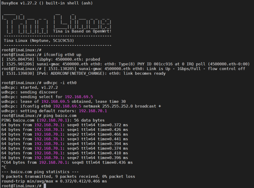
When the software is used, the eth network port must be up first:
ifconfig eth0 up
Then configure ip, gw, dns server, etc. Tina integrates these operations, only need:
udhcpc -i eth0
At this point, you can directly ping the Internet URL, as shown in the figure:
D1-H Tina v1.0 version
D1-H Tina public beta v1.0 version adds br-lan, which requires manual configuration:
ifconfig br-lan 192.168.11.11
At this time, go to ping the router address to test:
ping 192.168.11.11
40pin
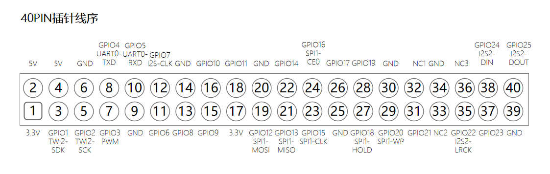
*The square mark in the lower left corner of the picture is 0, which corresponds to the square solder joint on the back of the development board
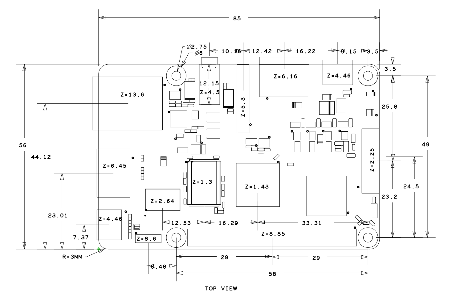
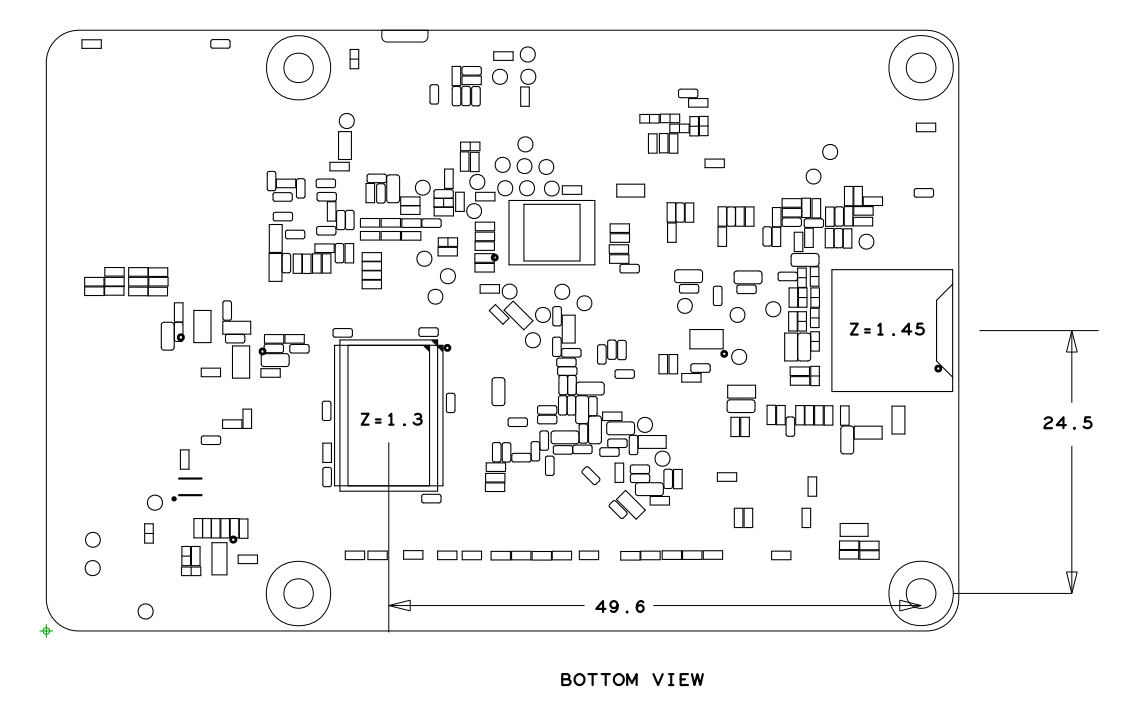
Plate and frame spacing diagram